


Plug-and-Play (PnP)

What Is Plug-and-Play (PnP)?
Plug and play was originally a term for computer hardware. When a new external device is added to the computer, the hardware resources can be automatically detected without needing reconfiguration or manual driver installation. Later, the meaning of hot plugging came into being, which refers to directly adding or removing hardware devices, such as unplugging and plugging USB, while the computer power is on.
In data communications and network solutions, plug-and-play means that after network equipment and access terminals are connected to the network, they can automatically access the network to complete configuration and deployment without manual configuration.
Why Does the Campus Network Need Plug-and-Play?
With the rapid development of network technology, the scale of enterprise networks is also expanding. Enterprise customers need to manage and maintain hundreds to thousands of devices, consuming work in the early planning and deployment stages, such as initial equipment installation. The time spent on configuration and equipment upgrades accounts for one-third or more of the entire network management and operation cycle, and most of these tasks are simple and repetitive. Therefore, customers urgently need to simplify the installation of network equipment, management during deployment and subsequent equipment software upgrades, thereby improving efficiency.
In addition, with the continuous popularization and application of the Internet of Things, the types and number of terminals accessing campus networks are increasing. Especially in large and medium-sized campus networks, in addition to PCs and mobile phones, access terminals also include IP phones, printers, and cameras. Many different types of terminals need to be connected to the campus network, making terminal management on the campus intranet very difficult. Because the traditional network management system can only view the IP and MAC of the access terminal, it cannot perform more detailed management of the terminal. If different network services and policies need to be planned and deployed for various terminals, the administrator needs to plan and deploy different network services and policies for each terminal type. Manual configuration of type terminals makes the service configuration complex and the operation tedious. Automatic identification and plug-and-play of terminal equipment are also urgently needed.
The plug-and-play solution is designed to help users simplify the network installation process, greatly improve network management efficiency and operation and maintenance, and effectively reduce labour and time costs. It has the following advantages:
Visualization: The operation process of network administrators and installation engineers is a fully graphical operation interface, including visualization of configuration interface and visualization of network planning.
High efficiency: By pre-deploying services on the SDN controller, the actual deployment process is shortened from end to end. Manual deployment can be completed in a few hours instead of several days.
Fewer errors: All configurations are performed graphically through the SDN controller, reducing the probability of command line configuration errors; connection errors can be graphically sensed in real-time through the SDN controller for quick troubleshooting.
What is the Plug-and-Play Process for Network Equipment?
Taking switches as an example, in the cloud park network, the network is designed in a layered tree, and there are a large number of switches below the core layer. Plug-and-play through the convergence layer and access layer switches can improve the opening efficiency and simplify the opening workload.
The core layer switches complete the southbound docking with the SDN controller through the command line, and then the core layer switches are used as the root devices of the management subnet, and the below-core layer switches are brought online in the SDN controller through the DHCP method, so as to realise the plug-and-play of the below-core layer switches.

As shown in the figure above, the aggregation SwitchA Plug and Play process is as follows:
The administrator deploys the DHCP server function on the core layer device (or it can be a separate DHCP server device in the network), enables the DHCP function in VLANIF1, and configures the DHCP Option 148 option, which contains the NETCONF enable state of the device, the URL/IP of the SDN controller, and port number information.
After the below-core SwitchA boots up with an empty configuration, it will by default use VLANIF1 to initiate a request to the DHCP server.
Since all ports of the switch are added to VLAN 1 by default when it is shipped from the factory, the core switch and the switch that initiates the request are interoperable within VLAN 1.
Once the core switch, which is the DHCP server, receives the request, it responds to SwitchA with a DHCP message carrying the Option 148 option.
SwitchA enables the NETCONF function based on the contents of the Option 148 option and also obtains the URL/IP and port number information of the SDN controller.
SwitchA obtains the URL/IP and port number information of the SDN controller, it uses the URL/IP and port number information of the SDN controller to register authentication with the SDN controller.
After SwitchA registers and authenticates with the SDN controller to go online, the SDN controller automatically sends the configuration to SwitchA according to the preconfiguration set by the administrator (including the PnP VLANs), completing the opening of SwitchA to achieve plug-and-play.
PnP VLAN
In the network device plug-and-play process, there is an important concept, PnP VLAN, also called self-negotiating management VLAN, which refers to the VLAN used by the SDN controller when it nano manages switches or APs.
Initially, aggregation switches and access switches use function VLAN 1 to achieve registration on the SDN controller online, in order to improve the reliability of the network, administrators generally do not use VLAN 1 as the management VLAN, because VLAN 1 is the default VLAN of the switch, and all the ports of the switch are added to VLAN 1 by default, so it is easier to generate broadcast storms in VLAN 1 and affect the service communication. affect service communication. Therefore, after the aggregation switch and access switch go online with VLAN 1, they need to automatically switch to the set management VLAN according to the SDN configuration, and this automatically switched management VLAN is called PnP VLAN.
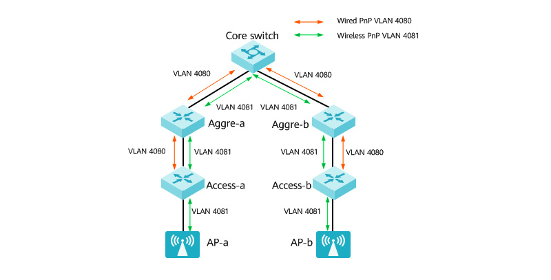
In the campus network, for the convenience of network maintenance, the PnP VLANs used in wired and wireless networks are generally set as different VLANs, which are called wired PnP VLANs and wireless PnP VLANs, respectively.The PnP VLANs used by the switches are called wired PnP VLANs, and the VLANs used by the APs are called wireless PnP VLANs.
The PnP VLAN switching process is as follows:
The aggregation device and the access device register online with the SDN controller using VLAN 1.
The SDN controller issues the preconfigured PnP VLANs to the aggregation device and the access device.
The aggregation device and access device re-register on the line using the negotiated PnP VLAN to achieve plug-and-play.


share

