


Switch Stacking vs. MLAG

What is Switch Stacking?
A switch stack in networking is a configuration of multiple stackable switches connected via stacking cable and virtualized as a logically single device for data forwarding. It is a scalable solution to expand network capacity while not having trouble managing multiple physical devices. Also, adding or removing a switch in the stack won't affect the stack system's performance. Once one link or switch in the stacked switch unit fails, the stack system can continue to transfer data.
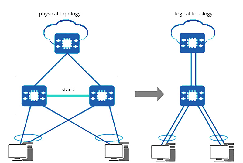
F1: Ethernet Switch stacking topology
Some mainstream brands have slightly different names for this function, such as “Cisco StackWise”, “Aruba VSF”, and “Huawei istack”. Cisco even set terms to define various Cisco switch stacking versions. For example, Cisco's StackWise technology supports a maximum of 8 stacks, and StackPower supports a maximum of 4 stacks.
Most of the QSFPTEK S5300 and S7300 series campus switches are stackable managed switches. The table below shows how many switches can be stacked. Some models support stack 2 switches, and others support stack 8 switches.


What is MLAG?
MLAG (Multi-chassis Link Aggregation Group or Multi-chassis LAG) is a method to form the link aggregation group (LAG) among multiple devices for redundancy — When one of the switches fails, the system can still work. Though the IEEE 802.1AX-2008 standard that defined LAG does not mention Multi-chassis LAG, MLAG has become a widely applied link aggregation approach. It adds node-level redundancy to the legacy link-level redundancy that LAG provides.
The implementation of MLAG is proprietary, which means MLAG cannot be configured between switches of different vendors. Simply put, the mechanism is to connect two switches via peer-link and form a link aggregation group to act as a logically single device. More switches can be added to the link aggregation group using MLAG. MLAG topology can largely scale network capability, boost system reliability, and simplify management.
All QSFPTEK S5600 and S7600 series data center switches support MLAG.
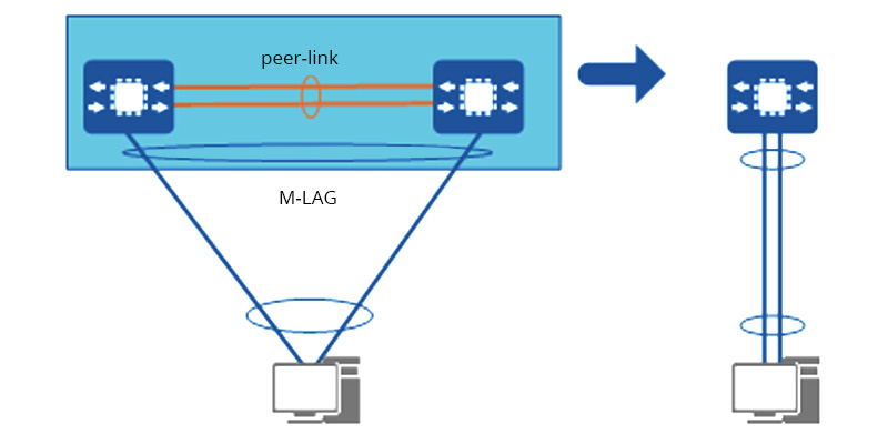
F2: Switch MLAG topology
What is LACP?
LACP (Link Aggregation Control Protocol), based on IEEE 802.3 ad standard, is a protocol that provides a method to realize dynamic link aggregation and de-aggregation. IEEE 802.3 ad LACP is to allow devices to automatically form link aggregation and perform data forwarding according to their own configuration. LACP aggregates multiple physical links into a logically single link, increases the network bandwidth, and delivers link redundancy. Four 1G link is a virtual 4G link. In the event one physical link fails, the other link in the LACP group will balance the load.
All QSFPTEK switches are LACP switches.
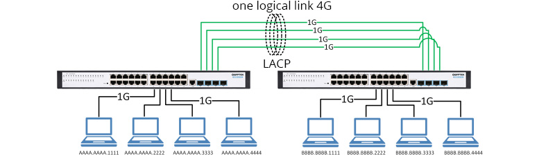
F3: LACP topology
Stacking vs M-LAG, What's the Difference?
It seems that link aggregation and stacking switches for redundancy are similar scalable solutions. However, they are quite different in many factors.
Cross-Vendor Interoperability
Stacking and MLAG are proprietary, which means you cannot implement switch stack and MLLAG with switches from different vendors. In most cases, switches are limited to the same series of product lines. However, LACP can be configured among multiple switches from different vendors.
Bundle Quantity and Scalability
Network switch stacking port capacity is limited by the maximum switch stack quantity specified by vendors. MLAG is not subject to this restriction. It is easy and flexible to add another switch east and west or north and south to form a new MLAG. LACP itself has no ability to bundle multiple switches, instead, the LACP mode is configured in multiple ports in a single switch and builds up links with another switch. Whether and how many ports are capable to configure LACP are assigned by vendors.
Configuration and Management
As the switch stack can be viewed as logically a single device, it has a unified IP/MAC address. Thus you should only configure and manage one device. However, the MLAG switches have to be configured and managed individually since there is no virtual system IP/MAC. The networking complexity of Ethernet switch stacking is also easier than MLAG.
Upgrading Complexity
Though stacking simplifies management for a single control panel, it reduces its reliability. MLAG has higher reliability for it has dual control and management panel. When upgrading the network, MLAG can truly realize uninterrupted services for ultra-short interruption time and no changes to the original network architecture.
Reliability
The load balancing function gives MLAG higher reliability. When the access device connects to the M-LAG device group through Eth-Trunk, the M-LAG member devices will jointly forward the traffic after receiving it from the edge device sent by link bundle load balancing.
Application
MLAG is usually applied to the spine-leaf network architecture and the core/aggregation layer of the three-tier network architecture to provide ultra high-reliability for servers or switches. It has separate control panels and an isolated fault domain, which gives it a better ability to balance load across links. The major consideration of MLAG deployment is higher reliability and short interruption time for upgrading, and not minding the difficulty of networking maintenance.
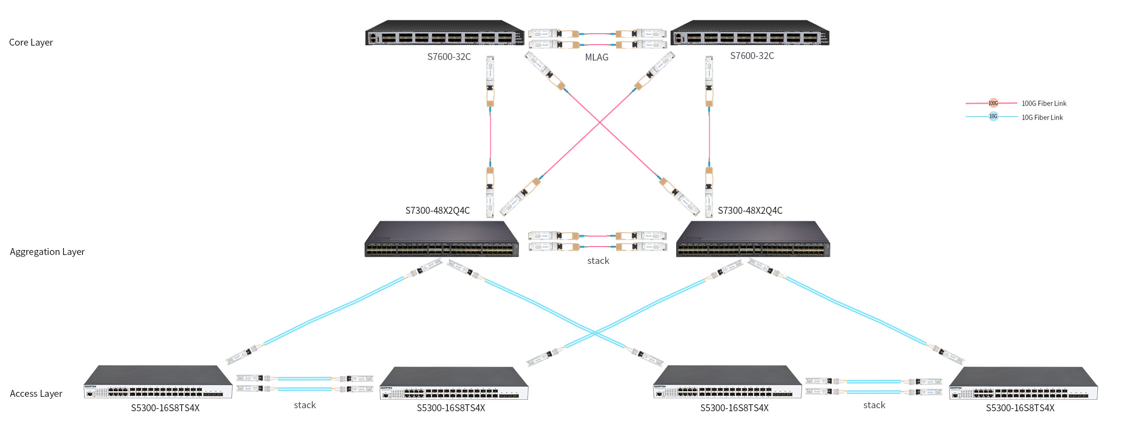
F4: MLAG and stacking applied in three-tier network architecture
Stacking is often used in the network access/aggregation layer where the stack units are located closely. The typical scenario of stacking is when the ports for edge devices of the existing switch equipment are insufficient. Stack switches are to supplement port quantity and increase network bandwidth in a flexible and easy way.
QSFPTEK MLAG vs Stackable Switches Introduction
QSFPTEK switches offer both MLAG and stacking solutions to help users scale network bandwidth. The table below lists specific switch models that support MLAG or stacking.
Both stackable switches and MLAG link aggregation switches use uplink ports for stocking or link aggregation.
The following part will give a detailed illustration of how to use the uplink ports as stack ports for network switch stacking.
For models that support stacking 2 switches, take S5300-24T4X 24 port gigabit switch as an example, which has 4 10G SFP+ uplinks. You can choose one of the following solutions as stacking cables to connect the two 10G SFP+ uplink ports to each device:
• a pair of 10G SFP+ to 10G SFP+ DAC cables
• a pair of 10GBASE-SR SFP+ transceivers and OM3/OM4 MMFs
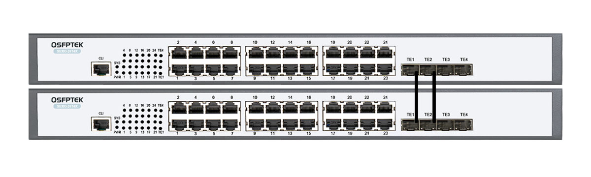
F5: 2x S5300-24T4X in a stack
For models that support stacking 8 switches, say S7300-48X2Q4C 48 port 10Gb switch, you can use the 10G SFP+ ports, 40G QSFP+ or 100G QSFP28 uplink ports for stacking.
If using 100G QSFP28 uplinks for stacking, two typical stacking solutions are as follows:
• 8x a pair of 100G QSFP28 to 100G QSFP28 DAC cables
• 8x a pair of 100GBASE-SR4 QSFP28 transceivers and OM3/OM4 MMFs
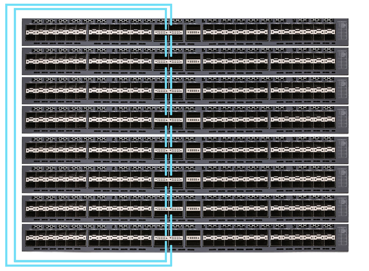
F6: 8x S7300-48X2Q4C in a stack
Use 100G ports for two-to-two connection, The connectivity guide:
• the NO.3 and NO.4 100G ports of switch 1 are connected to the NO.1 and NO.2 100G ports of switch 2
• the NO.3 and NO.4 100G ports of switch 2 are connected to the NO.1 and NO.2 100G ports of switch 3
• the NO.3 and NO.4 100G ports of switch 3 are connected to the NO.1 and NO.2 100G ports of switch 4
• ...
• Finally, the NO.1 and NO.2 100G ports of switch 1 are connected to the NO.3 and NO.4 100G ports of switch 8.
Conclusion
In general, stacking has the advantages of relatively simple configuration and networking design, but its flexibility, reliability, and upgrade complexity are not as good as M-LAG. The features of high coupling and high networking flexibility of MLAG make it more reliable but require more complex networking and maintenance.
QSFPTEK provides switch MLAG, stacking and LACP 802.3 ad switch to meet the ever-increasing bandwidth network trend. For switches used in the access/aggregation layer and requiring a simple solution to add port quantity, we recommend S5300 or S7300 series stackable switches, which can expand your network capacity while simplifying management. For bandwidth-hungry applications in the core network for the spine or leaf architecture, we recommend deploying S5600 or S7600 series switches to deliver high reliability and scalability for future-proofing your network. Please feel free to consult our expert for chosen guide.


share
