


Ethernet Patch Cable Length and Bends: How to Influence Network Performance

Copper Ethernet cables continue to play an irreplaceable role in modern enterprise networks, data centers, and smart manufacturing. The length and curvature of the Ethernet copper cable determine link performance, bit error rate, transmission stability, and network bandwidth. As the cable length increases, its insertion loss also increases. Excessive curvature increases signal reflection and crosstalk, leading to higher bit error rates and unstable throughput. Therefore, maintaining the appropriate length and reasonable curvature of the Ethernet copper cable is one of the easiest ways to ensure signal transmission quality. This article will take you deeper into understanding why the length and curvature of copper Ethernet cables affect link performance.
How Cable Length Impacts Ethernet Patch Cable Performance
In copper cable networks, the longer the link, the farther the signal needs to travel, resulting in higher accumulated insertion loss. Furthermore, since copper cables transmit electrical signals, longer links are more susceptible to electromagnetic interference, leading to a decrease in signal transmission quality. Electrical signals also travel slower in copper cables than optical signals in fiber optics, resulting in higher latency over long distances.
How Increased Length Leads to Increased Signal Loss
As copper cable links become longer, various attenuation effects accumulate:
First, insertion loss increases with length; the attenuation rate accelerates with increasing frequency over distance.
Second, return loss decreases, and more impedance discontinuities lead to more severe reflections, increasing the burden on the transmitting DSP.
Third, reduced ARC margin causes crosstalk and attenuation to compound, increasing the probability of transmission errors.
Finally, increased length also increases latency and jitter, although the absolute values may be small, they can impact performance in latency-sensitive applications.
While high-performance copper cables, such as Cat6a, Cat7, and Cat8, reduce crosstalk through shielding and tighter twisting, they are still affected by increasing attenuation over longer distances, higher frequencies, and greater link sensitivity.
Typical performance of different cable types over long distances:
Cat5e: Stable 1G, but PoE loads and high-noise environments significantly reduce margin.
Cat6: Stable 1G, 10G performance begins to fluctuate with accumulated insertion loss; suitable for ideal environments of 37–55m.
Cat6a: Reliable 10G within 100m, but more sensitive to cumulative reflections from cabling quality.
Cat7: 10G remains intact in short-distance applications, with stronger shielding and low crosstalk, but attenuation still increases with length.
Cat8: Excellent 25G/40G performance in short-distance links, but beyond the applicable distance, the signal-to-noise ratio drops rapidly and the bit error rate increases.
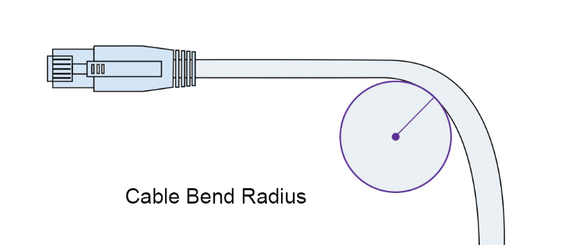
How Cable Bend Impacts Ethernet Patch Cable Performance
Compared to length, the degree of cable bending has a more direct and subtle impact on link performance. Copper cables rely on a precise twisted structure to maintain differential impedance and crosstalk immunity. Deformation can cause reflections, increasing crosstalk.
The Impact of Bending on Structure
Copper cables employ a tight twisted design to reduce interference. Excessive bending disrupts the twist pitch, altering differential impedance and increasing return loss. It can also cause localized compression, enhanced high-frequency reflections, and a higher bit error rate. Excessive bending can deform the shielding layer, reducing its anti-interference capability and increasing susceptibility to noise.
The Impact of Bending on Performance
Bending Ethernet copper cables primarily affects three key parameters: insertion loss, return loss, and near-end crosstalk.
When the bending radius exceeds the minimum bending radius, the increase in insertion loss is limited and negligible for most networks.
When the bending radius approaches the minimum bending radius, there is a slight interference with insertion loss, return loss, and near-end crosstalk, but stable multi-gigabit performance can still be maintained.
However, when the bending radius is less than the minimum bending radius, insertion loss increases significantly, and return loss and near-end crosstalk deteriorate markedly, affecting high-speed links and PoE equipment.
Furthermore, when the copper cable is folded or subjected to extreme bending, insertion loss exceeding 3dB may cause intermittent speed drops or complete link failure.
How to Maintain Copper Cable Signal Quality During Deployment
Control Link Length and Optimize Cabling
Maintaining a straight copper cable path during deployment is the simplest way to improve performance. To avoid cable slack, cable length planning is necessary before deployment. Deploy copper cables within the recommended length, keeping the cables as compact as possible to ensure link performance.
Maintain a Reasonable Bending Radius
Bend copper cables according to the product's recommended minimum bending radius. The minimum bending radius is 4 times the cable's outer diameter under dynamic conditions and 8 times the cable's outer diameter under fixed conditions. This effectively prevents crosstalk and reflections.
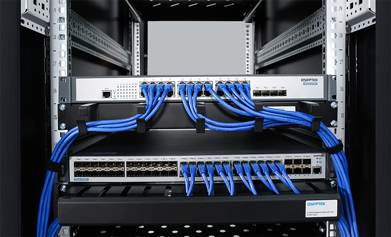
Strengthen Cable Management and Securement
Using cable management equipment, such as cable management racks, can effectively prevent localized pressure and bending caused by excessive density, and prevent external knots.
Test the Link
After deployment, use professional testing equipment to test the link, mainly measuring its insertion loss, return loss, NEXT, link speed, and whether the PoE function is intact.
QSFPTEK Offers High-Quality Ethernet Patch Cable
QSFPTEK provides Ethernet cables rigorously tested with Fluke equipment. Each cable undergoes stringent testing by Fluke and Wired T568B to ensure superior performance. Features include multi-strand cable, RJ45 modular connectors with 50μ'' gold-plated contacts, and a PVC sheath for enhanced protection, significantly extending cable lifespan.
Conclusion
The length and bend of an Ethernet patch cable both determine its performance. Longer cables experience greater losses, while greater bends lead to reflections and crosstalk. When deploying a network, cabling needs to be planned to ensure Ethernet cables are kept within reasonable length and bend limits. This ensures stable network transmission and avoids potential problems.


share

