


S5300 Series Switch Stacking Guide: Configuration & FAQs

Switch stacking technology allows multiple stack switches to be connected with stacking cables and thus operate as a single logical unit, increasing the number of expansion ports, increasing bandwidth, and simplifying networking. With switch stacking technology, the network's capacity can be significantly increased. Most QSFPTEK S5300 series stackable switch supports the switch stacking function. This article will introduce the details of switch stacking technology.
What is Switch Stacking Technology?
Switch stacking technology involves connecting multiple switches that support stacking features together over specific stacking cables. Thus, they are logically virtualized into a single switch device, and they are used as a whole for data forwarding. Switch stacking technology is a widely used network virtualization technology today.
Switch stacking technology can improve the reliability of the system. By using the switch stacking technology, two stack switches can back up each other, and when one of them goes down, the other switch can take over to ensure the normal operation of the system, and the stacked switches form a redundant backup through link aggregation. The number of ports can also be expanded. When the port density of the original switch cannot meet the access demand, the number of ports can be expanded by adding new switches using the stacking system to increase the network bandwidth. Switch stacking technology also allows for a more simplified network stacking architecture. After multiple devices are virtualized into a single logical device, stacked switches do not need to use loop-breaking protocols such as MSTP, thus simplifying network configuration.
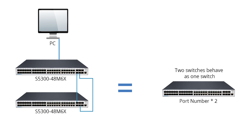
The following figure shows two S5300-48M6X switches stacked:
How Does Switch Stack Work?
Switches can be stacked with DAC high-speed cables, optical modules, or stacking-specific cables. The switch stacking system includes a switch master and stack slaves. Usually, the switches in the stack other than the stack master are referred to as stack slaves. The stacking master switch is the core switch that manages the stacking slave switches and holds the operational configuration files of the entire stacking switches.
Users can log in to the stacking system through the stacking master switch to unify the configuration and management of all switches in the stacking system. When the master switch fails, the stacking system will select the next switch to switch to the master switch based on the settings, thus not affecting the operation of the entire network.
QSFPTEK S5300 series stack switches support up to 8 switches stacking together. No matter how many stacked switches there are in the switch stacking system, only one stack master switch is allocated in the whole system, and users can manage and maintain the entire switch stack through the master.
The following figure shows two S5300-24T6X switches stacked:

The following are the maximum number of stacks supported by different S5300 series switches:
Typical Stacking Topologies
Two typical topologies for stacked connections are available, chain topology and ring topology. Each has benefits and drawbacks.
With the chain topology, no physical connection is required between the first and last stack members, which is suitable for stacks that are relatively far apart. But if a stack link fails, the stack will split.
With ring topology, in case one of the stacking links has failed, the ring topology turns into a chain topology and will not disrupt the normal operation of the stacking system. Therefore, the ring topology provides higher reliability than the chain topology.
A ring topology, however, requires the first and last member switches in the ring topology to be physically connected. Thus, ring topology with DAC cables or other stacking cables over short distances is not suitable for long-distance transmission. QSFPTEK S5300 series stacking switches support both chain topology and ring topology.
The Switch Stack Configuration
The network stacking configuration has the following steps:
1. Before making the connection, please make sure that the connected devices are in a power failure. Use DAC/AOC high-speed cables or optical modules with fiber cables for switch stacking connections. Note that the number of switches stacked should not exceed the maximum stacking number.
2. Power on the switches in turn and complete the stacking configuration of all switches, such as member ID, priority value, etc.
3. After completing the configuration of all switches, reboot and allocate the roles of each stacked switch member.
4. After the stacked switches finish rebooting, the administrator can only configure the network and check the interface information through the master switch. The master switch can show all interfaces.
Conclusion
In conclusion, the S5300 series switches are a new generation of intelligent switches designed for carrier IP metro, campus, and enterprise networks, and are available in different models, including L2/L3 switches, and PoE switches, and can meet the needs of multiple rates. It supports advanced functions such as ACL, QinQ, QoS, etc. Support uninterrupted upgrades, continuous forwarding, graceful restart, and redundancy protection.
Switch Stacking Q&A
1. What's The Difference Between Switch Stack vs Chassis?
Both stacked and chassis switches provide more ethernet ports combined with the network system and are managed through a single device. The difference between these two types of switches is that network stacking switches require stacking cables to connect them together. Chassis switches, on the other hand, have a certain number of fixed slots or various line cards for connection.
Comparing the difference between the two, the upfront investment is higher with a chassis switch. Switch stacking is less expensive and also leads to more regional long-distance stacking application scenarios.
2. The Difference Between Switch Stack vs MLAG
MLAG refers to multi-device link aggregation, where multiple physical links are combined into a single logical link. MLAG offers the benefits of high availability and high throughput. Both stacking and MLAG can provide link redundancy. Switch stacking technology is generally used in the access layer of enterprise networks, where stacked devices are easier to manage and less expensive to operate and maintain.MLAG is generally used in the access layer of data centers. The advantages include relatively less configuration of devices, higher ROI, and the ability to increase redundancy to a higher level.
3. The Switch Stacking vs. Switch Cascading vs. Clustering
Among the interconnection technologies of multiple switches, the most common ones are switch stacking, cascading, and clustering. Next, we will introduce the differences between the three.
Cascading allows you to connect switches through multiple ports to expand the number of ports and increase the capacity of the device. In principle, switches can be cascaded between any network equipment vendors. Unlike switch cascading, switch cascading remains logically independent and requires the configuration and management of each switch. The ports added by switch stacking share the total backplane bandwidth of the switch with the previous ports and cannot be shared by the cascaded switches.
Clustering is the management of multiple interconnected switches as one logical device. In a switch cluster, only one switch is managed, which is called a command switch to manage the other switches. This network switches only need to be assigned an IP address (which only the command switch needs). Unified management through command switches greatly reduces management intensity.
4. The Difference between Switch Stacking vs Uplink vs Trunking
The concept of "Uplink" refers to connecting the uplink port of a switch to another switch. Despite providing limited bandwidth increases, uplinks allow for connecting switches from different product families or vendors, thus providing greater flexibility.
In contrast, "Trunking" involves a connection between two layer 2 switches and is ideal for passing VLAN information between switches. Trunking is commonly utilized to form an inter-network, including LANs, VLANs, and WANs. This enables packets encapsulated for multiple VLANs to cross the same port while maintaining traffic separation among them.


share

