


Forward Error Correction (FEC) Guide: How Does it Work in the Essential Optical Transmission System

For numerous years, Forward Error Correction (FEC) has proven to be a highly effective tool within the cable industry. Notably, a significant enhancement in performance within the DOCSIS 3.1 specifications was accomplished by transitioning from the previously utilized Reed-Solomon (RS) FEC to a new coding scheme known as low-density parity check (LDPC), which offers improved performance. Likewise, FEC has become an essential component in high-speed optical transmission systems, particularly in the current era of coherent optical transmission.
What is Forward Error Correction?
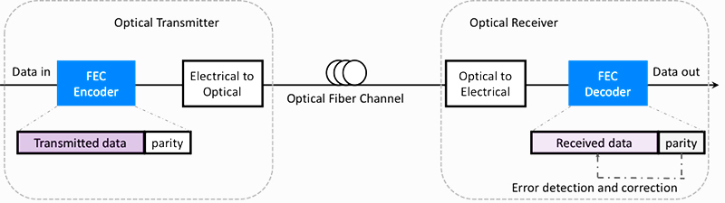
FEC stands for Forward Error Correction, a proficient digital signal processing technique to enhance the bit error rate of communication links. This method involves adding redundant information, specifically parity bits, to the data at the transmitter side. Subsequently, the receiver utilizes this redundant information to identify and rectify errors that may have occurred during transmission. The depicted diagram illustrates that the signal encoding carried out at the transmitter necessitates accurate decoding by the receiver to extract the original signal information. It is imperative to define and implement encoding rules precisely to prevent misinterpretation of information during signal decoding. Successful interoperability is only achieved when both the transmitter and receiver adhere to and enforce identical encoding and decoding rules.Successful interoperability is only achieved when both the transmitter and receiver adhere to and implement identical encoding and decoding rules.
Forward Error Correction (FEC) is a crucial component that must be specified to facilitate the creation of interoperable transceivers utilizing optical technology across point-to-point links. Present industry trends are oriented towards eliminating proprietary elements and promoting interoperability, primarily as operators advocate for more open and disaggregated transport in high-volume, short-reach applications.
When evaluating the appropriate FEC for a new specification, it is essential to take into account several key metrics, such as:
Coding Overhead Rate: The ratio of redundant bits to information bits.
Net Coding Gain (NCG): The enhancement in received optical sensitivity with and without employing FEC, correlated with the increasing bit rate.
Pre-FEC BER Threshold: A predefined threshold indicating error-free post-FEC transmission, determined by NCG.
Other considerations: These encompass factors like hardware complexity, latency, and power consumption.
The Development Process of FEC
A pivotal decision in FEC coding and decoding involves choosing between Hard-Decision FEC (HD-FEC) and Soft-Decision FEC (SD-FEC). HD-FEC makes binary decisions based on exact thresholds, determining whether 1s or 0s have occurred, while SD-FEC makes decisions based on probabilities, assessing the likelihood of a 1 or 0 occurrence. SD-FEC can offer a higher Net Coding Gain (NCG) to approach the ideal Shannon limit, albeit at the cost of increased complexity and greater power consumption.
The first-generation FEC code standardized for optical communication is the Reed-Solomon (RS) code, commonly used for long-haul optical transmission per ITU-T G.709 and G.975 recommendations. In the RS implementation, each codeword comprises 255 code word bytes, with 239 bytes for data and 16 for parity, often denoted as RS(255,239) and referred to as Generic FEC (GFEC).
In the second generation of FEC codes recommended by ITU-T G.975.1, several FEC coding schemes are advised for high-bit-rate dense wavelength division multiplexing (DWDM) submarine systems. Concatenated coding schemes with iterative hard-decision decoding were commonly utilized to improve Net Coding Gain (NCG). A notable illustration is the Enhanced FEC (EFEC) specified in G.975.1 Clause I.4, specifically designed for 10G and 40G optical interfaces.
The third-generation FEC incorporates soft-decision or iterative techniques, such as Block Turbo Code and LDPC (Low-Density Parity-Check) code.
In first and second-generation Forward Error Correction (FEC) technologies, the decoding process typically relies solely on the algebraic structure of the code. The demodulator supplies the decoder with a binary sequence, where the demodulator's role is limited to making 0 or 1 decisions based on the received sequence. This particular decoding approach is known as Hard-Decision (HD-FEC). The various types of hard decision FEC are compared as outlined below:
In the third generation of Forward Error Correction (FEC), the Soft-Decision (SD-FEC) method is employed, representing a probabilistic decoding approach. This technique involves conducting multi-bit quantization on the voltage samples the demodulator provides. The quantized data is subsequently forwarded to the decoder, where the algebraic structure of the code is decoded.
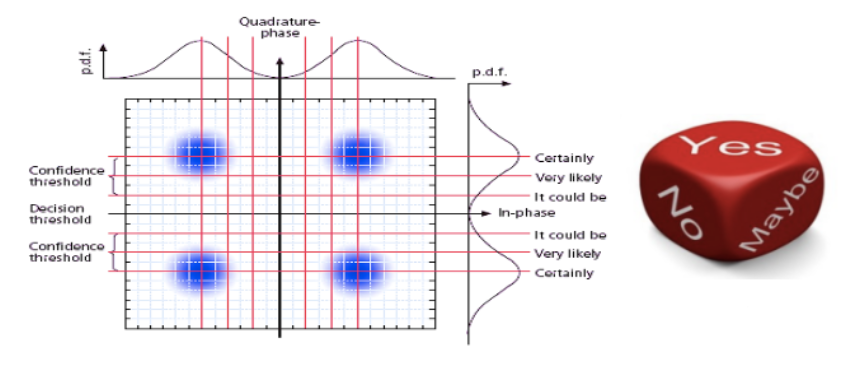
As depicted in the above illustration, hard decision employs a single threshold for quantizing one bit, whereas soft decision utilizes multiple thresholds to quantize recovered symbols, providing one-bit information along with additional several-bit probability (confidence) data. This can be likened to introducing a "Maybe" category between "YES" and "NO." With an equivalent overhead ratio, the Non-Coherent Gain (NCG) of SD-FEC is 1-1.5dB higher compared to that of hard-decision HFEC.
Currently, 100G and beyond 100G wavelength division systems primarily utilize SD-FEC or a hybrid encoding approach, combining SD-FEC with EFEC/HFEC. Using the LDPC definition established by the LOFC conference as a reference, the table below illustrates its overhead and NCG.
Based on the preceding data, we can conclude that a higher FEC overhead correlates with a greater coding gain.
FEC finds its application in high-speed communication, particularly in 25G, 40G, and 100G scenarios, with a pronounced emphasis on 40G and 100 G. The optical signal undergoes degradation during transmission due to various factors, leading to potential misjudgments at the receiving end. These misjudgments might involve mistaking a "1" signal for a "0" signal or vice versa. The FEC function involves transforming the information code into an error-correcting code through the channel encoder at the transmitting end. The channel decoder at the receiving end then decodes the received code, pinpointing and rectifying errors within the error correction capability if they fall within the scope of correctable errors (discontinuous errors), thereby enhancing signal quality.
100G QSFP28 Optical Module With FEC Function
The incorporation of FEC functionality is bound to introduce certain packet delays during the correction of bit errors. As a result, it is not mandatory for all 100G QSFP28 optical modules to activate this feature. For instance, by the IEEE standard protocol, it is advised to refrain from enabling FEC when utilizing the 100G QSFP28 LR4 optical module. Conversely, certain other optical module models are suggested to have FEC enabled.
Diverse companies offer 100G QSFP28 optical modules with variations in their specifications. The table below illustrates whether it is advisable to activate the FEC function when utilizing the following QSFPTEK 100G QSFP28 optical module:


share

